Heatsink Guide - AnandTech Heatsink Testing Methodology
by Tillmann Steinbrecher on January 21, 2000 11:55 PM EST- Posted in
- Guides
 Resistors?
Many people think of tiny little sticks with colorful stripes when they hear
this word. But not all resistors are that small, and the ones chosen for the
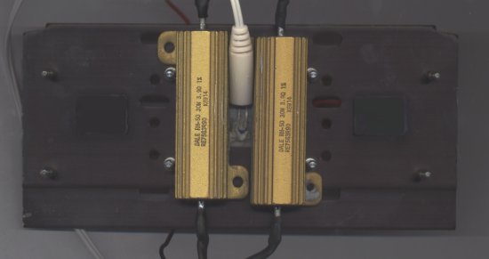
»simulator« are rather large ones, as you can see on the image to the right.
Two 3.9 Ohm resistors with a tolerance of only 1% are being used for the simulator (the same kind of resistor is used in some high end amplifiers, for example). They are powered with 12V, which results in a total heat emission of 73.84 Watts (36.92 Watt per resistor, as you can easily calculate using the formulas U=R*I and P=U*I).
Close to 74 Watts power dissipation - that's quite a lot; more than any current x86 CPU consumes. But with a higher thermal load, performance differences between different heatsinks will become more obvious, and this is the reason why the simulator has such a high wattage.
The two resistors and the thermal sensor are glued to the SECC1 thermal transfer plate using thermoconductive epoxy.

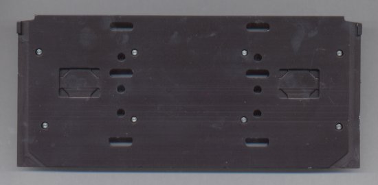
From the front side, the simulator looks like an actual Athlon CPU...

... but on the back, the two resistors have replaced the Athlon CPU core.
The thermal sensor is located between the resistors.


0 Comments
View All Comments